4 Things to Know About Antenna Tuning in 4G / 5G Smartphones
April 25, 2019
 Antenna
efficiency plays a critical role in overall smartphone RF performance.
However, current trends in smartphone industrial design and
RF requirements — especially with the upcoming transition to
5G — mean that smartphones must fit more antennas into less space
and/or increase the bandwidth of existing antennas.
Antenna
efficiency plays a critical role in overall smartphone RF performance.
However, current trends in smartphone industrial design and
RF requirements — especially with the upcoming transition to
5G — mean that smartphones must fit more antennas into less space
and/or increase the bandwidth of existing antennas.
In short, antenna tuning is more important than ever. In this blog, we
introduce four key elements to understand about antenna tuning in 4G and 5G
mobile devices.
Background: Why is antenna tuning needed?
The design of the RF front end (RFFE) in modern mobile phones has become increasingly complex due to the growing number of frequency bands, features and modes in which the phone needs to operate. More antennas are required to deliver higher data rates using carrier aggregation (CA), 4x4 MIMO, Wi-Fi MIMO and new wideband 5G frequency bands, increasing the number of antennas in the smartphone from 4-6 to 8 or more. At the same time, the space available for the mobile system antenna has shrunk, lowering the antenna’s efficiency.
Some of this lost performance can be recovered with antenna tuning. Without tuning, the antenna performs well in a limited frequency range, but adding antenna tuning can optimize performance across a broader frequency range.
Antenna tuning systems, like impedance tuners and aperture tuners, can support the increased bandwidth and carrier aggregation demanded of LTE smartphones. They allow antennas to be efficient across the entire LTE and 5G bands from 600 MHz to 5 GHz, while saving battery power and enabling sleek and thin phone designs.
But implementing antenna tuning requires in-depth knowledge of how to apply the technology for each application. Let’s take an introductory look at four elements:
- Impedance versus aperture tuning
- Choosing the right components for your tuning application
- On resistance (RON), off capacitance (COFF) and removing unwanted resonances
- Aperture tuning and CA
Glossary of Terms
- CA: carrier aggregation
- COFF: off capacitance
- GND: ground
- MIMO: multiple input/multiple output
- PIFA: planar inverted-F antenna
- RFFE: RF front end
- RON: on resistance
- RSE: radiated spurious emissions
- SP4T: single pole, four throw
- TIS: total isotropic sensitivity
- TRP: total radiated power
#1: What’s the best approach — impedance or aperture tuning?
The radiation pattern and efficiency of an antenna are dependent on its size, shape, housing, nearness to metal, and the shape and size of its ground plane. An untuned antenna has less efficiency than a tuned antenna; in contrast, the higher efficiency from a tuned antenna means it has more radiated power and increased range.
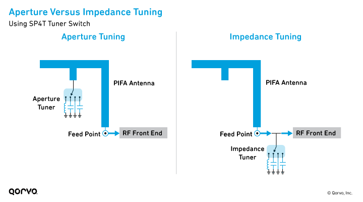
Smartphones can use two approaches to antenna tuning — impedance tuning and aperture tuning — which are shown in the figure below.
- Aperture tuning optimizes the total antenna efficiency from the antenna terminal’s free space, and it can optimize antenna efficiency across multiple bands. Aperture tuning can make a large impact on antenna efficiency for both transmit and receive communications, improving total radiated power (TRP) and total isotropic sensitivity (TIS) by 3 dB or even more depending on the application.
- Impedance tuning maximizes power transfer between the RF front end and the antenna, and it increases the TRP and TIS by minimizing mismatch loss between the antenna and antenna front end. Impedance tuning also helps to compensate for environmental effects such as a person’s hand position on a smartphone.
Today, aperture tuning is the primary method used in handsets to overcome
reduced antenna area and efficiency. Midtier and higher-end smartphones use a
combination of aperture and impedance tuning to support the ever-broadening
range of frequency bands — especially for 5G.
#2: How to choose the right tuning components
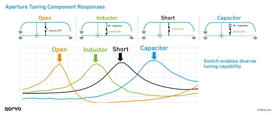
Adding tuning components like a capacitor or inductor between the switch and the radiating element can help further adjust the resonant frequency to support LTE and 5G bands. The image below shows the resonant frequency of an antenna when the switch is off, when it is on, and when an inductor or capacitor is inserted into the circuit.
It’s important to choose aperture tuning switches, capacitors and inductors with the best performance. Some guidelines include the following:
Tuner Switches:
- Use switches with low RON and COFF to minimize loss in the system.
- Use high-linearity tuner switches to avoid impact on radiated spurious emissions (RSE) and TIS.
- Switches must be multimode for tuning 2G/3G/4G/5G standard frequency ranges.
- Switches should be capable of handling high RF voltages for broadband antenna applications.
Tuning Components:
- Use capacitors with a capacitance value greater than 0.5 pF to avoid using a component with high tolerances.
- Avoid using inductors with an inductance value greater than
36 nH.
#3: RON, COFF and removing unwanted resonance
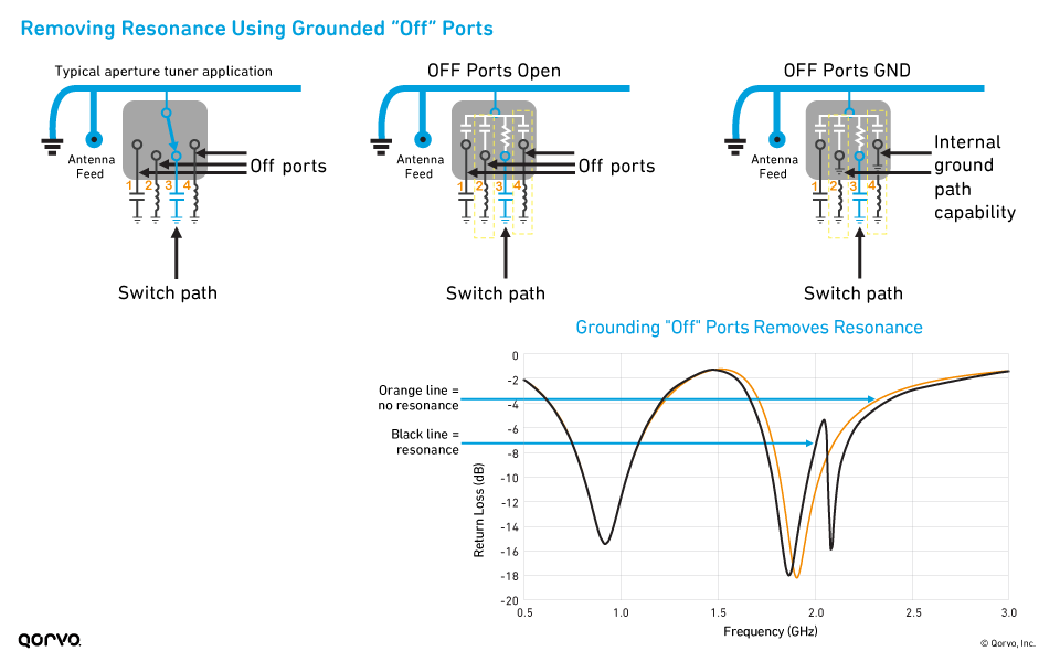
Two critical characteristics of aperture tuning switches significantly affect antenna efficiency: on resistance (RON) and off capacitance (COFF). Aperture switches are capacitive in their OFF (COFF) state, and they’re resistive in their ON (RON) state. If an inductor is connected to the RF port for tuning, then the combination of COFF and inductance will cause unwanted resonances. In other words, when the switch is in the OFF state, the resonance mechanism is destined to exist. To suppress this resonance, tuner switches have an internal switch to shunt to ground.
The next figure shows an SP4T tuner switch that is connected between an antenna and tuning elements, to tune the antenna to different frequency bands. The antenna is connected to a tuning capacitor via the RF3 port, whereas the other three ports are switched OFF. The ON state resistance between the antenna and RF3 port is replaced with RON, and the parasitic OFF state capacitance between the antenna and RF1, RF2 and RF4 ports is emulated using COFF. This ground path capability helps eliminate the resonances caused by the capacitances generated from the off-switch ports. In the image below, on the bottom right, the black line shows resonance, while the orange line shows no resonance.
Decreasing RON can improve antenna efficiency in both inductive and
capacitive tuning by several dB, with a large impact on a handset’s
overall RF performance. Low COFF is similarly important. However, RON and COFF
have differing impacts depending on the location of the antenna tuner and the
voltage distribution. Learn more about RON and COFF in our free e‑guide,
How to
Implement Aperture Tuning: Best Practices for 4G/5G Smartphones.
#4: Aperture tuning and carrier aggregation
CA combines two or more LTE carriers, often in different frequency bands, to deliver increased bandwidth and higher data rates. Due to the limited total number of antennas in handsets, this often means that a single antenna must communicate on two bands simultaneously.
Using aperture tuning switches can help meet smartphone requirements for CA:
- Aperture tuning is used to support the CA combination of Band 39 and Band 41, which is commonly used in China.
- Placing a switch near each frequency’s peak voltage allows high-efficiency tuning of each band with minimal impact on the other band.
- Placing a tuning switch near the peak voltage of a resonant frequency has
the greatest tuning effect on that frequency.
Go in depth: Antenna tuning for 5G smartphones
5G can’t happen without proper antenna tuning. To learn more about
aperture tuning in your mobile handset designs, download our free e-guide,
How to
Implement Aperture Tuning: Best Practices for 4G/5G Smartphones.
View our Antenna Tuning products.
Free E-Guide: How to Implement Aperture Tuning
Learn best practices for aperture tuning in 4G/5G smartphone antennas.

Have another topic that you would like Qorvo experts to cover? Email your suggestions to the Qorvo Blog team and it could be featured in an upcoming post. Please include your contact information in the body of the email.