For engineers, component data sheets provide a map for product design. A data sheet is the official document in which a vendor guarantees the parameters of one of its components. Without it, engineers would be designing in the dark. However, not all data sheets are created equal. Vendors don’t always show the same parameters, display the parameters in the same way, or follow the same test conditions. This means design engineers may have to guess which vendor’s part is best for their design. Ultimately, choosing the wrong part could mean the difference between a good or bad system design. This paper outlines some of the different ways data is presented in Wi-Fi product data sheets and highlights potential pitfalls to watch out for.
The Challenge
Knowing that component data sheets are often formatted differently, and specifications are not always presented in the same way, the key to selecting the right component is understanding which parameters are most important for your application, and to decipher what the specifications in the data sheet really mean for your system. It may also be necessary to ask the supplier for further information if it’s not included in the data sheet or get clarification on measurement conditions.
Wi-Fi CPE Design Considerations
Before we dive into examining the critical data sheet parameters, here’s a list of high-level considerations for Wi-Fi customer premise equipment (CPE) design. It may be helpful to keep these considerations in mind when reviewing data sheets, to ensure that the components you choose meet all key system requirements.
- Regional regulations:
- U.S. (FCC – Federal Communications Commission & IEEE – The Institute of Electrical and Electronics Engineers)
- EU (CE – The Centers of Excellence & ETSI – The European Telecommunications Standards Institute)
- Asia-Pacific
- IEEE specifications
- Thermal considerations
- Software considerations
- Coexistence and interference
- Whether the product is designed for indoor or outdoor use
- Unit size: sleek form factor for consumer applications or larger device for industrial settings
Critical Parameters for Wi-Fi Design and How to Interpret Them
A core set of critical parameters can mean the difference between good and bad Wi-Fi CPE design. Four of these parameters are typically published in component data sheets:
- Error vector magnitude (EVM)
- Spectral mask
- Harmonics
- Dual-band dual-concurrent (DBDC) operation
Two additional important design parameters are not typically included in data sheets and may require further research or analysis:
- Burst length or packet aggregation
- PC board landing pattern
Here’s additional context for why these parameters are important:
Error vector magnitude (EVM)
EVM is a measure used to quantify the performance of a digital radio transmitter or receiver. Noise (including phase noise), distortion and spurious signals can degrade EVM. Unfortunately, RF component manufacturers do not always specify this parameter in the same way. For example, some provide the component’s static EVM specification in data sheets, while others publish dynamic EVM. The difference is important because a real-world Wi-Fi application is pulsed: the PA pulses on each time it transmits data, then pulses off to save power.
- Static EVM is a measure of EVM when the component is continuously on. The downside of the static EVM measurement is that it does not reveal power amplifier (PA) transients. It doesn’t measure the behavior of the PA during transient surges (momentary bursts of energy induced in power, data, or communication lines). These PA transients are only revealed when switching the PA on or off.
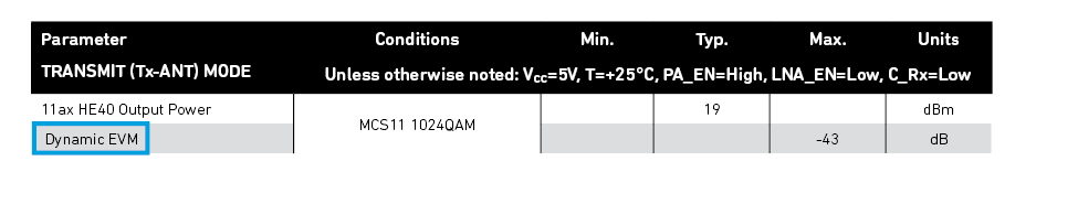
- Dynamic EVM measures the RF front-end (RFFE) PA in duty cycle mode (i.e. when switching on and switching off). Because a Wi-Fi application is pulsed, dynamic EVM more accurately reflects how the PA will behave in real world application.
As shown in Figure 1, there can be significant differences between the static and dynamic EVM measurements for the same component. In the data sheet, be certain to look for details of the duty cycle(s) under which a manufacturer tests the component. It’s recommended to test at both low and high duty cycles: the most complete picture of real-world performance is provided by testing at 10%, 50%, and 90% duty cycles. This test also reveals how quickly the PA turns on or off and whether it overshoots, both of which affect dynamic EVM. The differences between dynamic and static EVM also vary depending on the power level (Figure 1). This further underlines the need to test dynamic EVM, which is more in line with real-world applications.
Figure 1. Example PA EVM Test Comparing Pulsed and Static Duty Cycles (Note: EVM will differ based on design)
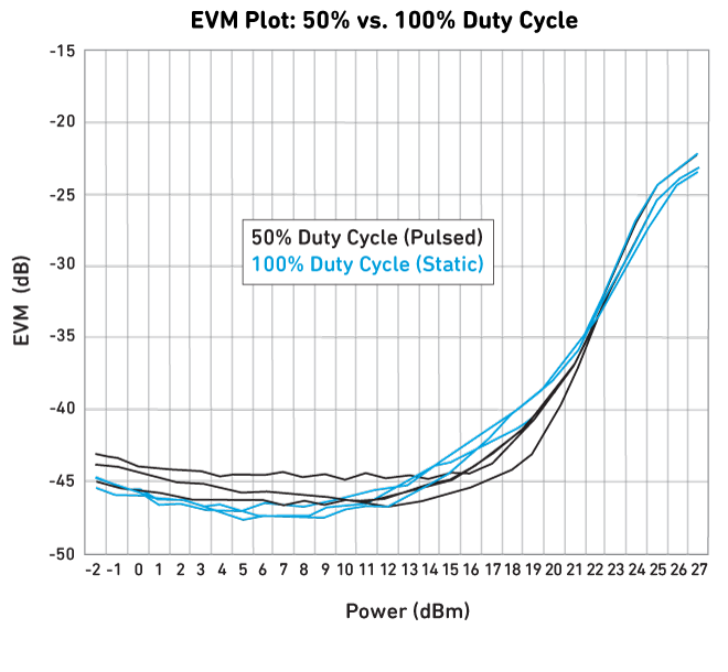
Figure 2. Dynamic EVM Data Sheet Specification
Spectrum mask
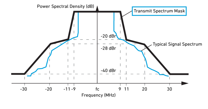
The transmit spectrum mask (also known as spectral mask) specification measures out-of-channel emissions that could cause interference. The spectral mask defines limits for the power contained in a specified bandwidth, relative to the total carrier power, at certain offsets from the center channel frequency (Figure 3). Spectral mask requirements are set by regulatory bodies such as the FCC to ensure that Wi-Fi devices do not unduly interfere with each other. Thus, you must meet this requirement or risk failing certification.
Figure 3. Transmit Spectrum Mask
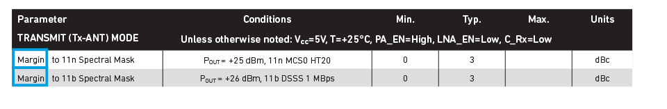
As with the EVM specification, the PA is the major contributor to the RFFE’s ability to remain within the spectral mask specification. When reviewing the data sheet, make certain that the RFFE spectral mask is specified with a margin of 2-3 dBc, as shown in Figure 4. The margin is the difference between the measured signal spectrum and the limit defined by the spectral mask. If you do not see this parameter specified with a margin, then the transmitted power is typically at the maximum limit. If that’s the case, the final production version of your Wi-Fi device could have difficulty meeting regulatory emission limits. If your application’s RF output power differs from your expectations, be sure to examine the PA module spectral mask specification to make sure the vendor included 2-3 dBc of margin.
Figure 4. Spectral Mask Data Sheet Specification with Margin
Harmonics
In RF applications, the term harmonic typically refers to a signal whose frequency is an integral multiple of the desired signal’s frequency. Harmonics are produced by non-linear components of the RF chain, and they can cause problems ranging from interference to receiver desense. So, it is important to ensure that the production of harmonic frequencies remains within acceptable limits. RF filters are typically used to ensure this is the case.
When reviewing harmonic parameters in a data sheet, determine whether the manufacturer’s published specifications were achieved using an RF filter. Some manufacturers’ data sheets show the harmonics parameters achieved when using an external discrete filter, but they do not openly disclose that a filter was used. You will need to carefully review the data sheet and application schematic to know whether an RF filter was used or not. If you cannot determine how the test was done, then ask the manufacturer’s applications engineer or product manager.
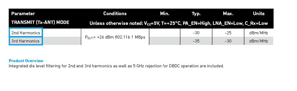
Some vendors embed an RF filter in their RFFE module and disclose this fact on the data sheet (Figure 5). It is always best to use an RFFE with an embedded filter, since in addition to minimizing out-of-band transmissions this approach reduces the potential need for external tuning and simplifies the overall bill of materials.
Figure 5. Harmonic Data Sheet Specification with Embedded Filtering
Dual-band dual-concurrent (DBDC) operation
The term dual-band dual-concurrent (DBDC) operation refers to routers that communicate simultaneously on the two Wi-Fi frequency bands (2.4 GHz and 5 GHz). Poor isolation between the frequency bands could cause receive and transmit issues (Figure 6). You always need to ensure that the RFFE has enough isolation between the transmit and receive signals, and to be certain that the receiver maintains adequate sensitivity.
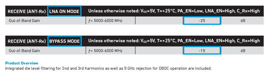
Some manufacturers add external or embedded filters to meet rejection criteria. In the example shown in Figure 6, the Wi-Fi chipset’s 5 GHz receiver can handle interference on its input of up to -20 dBm from the router’s 2.4 GHz transmitter, without the risk of receiver desense. By using an embedded 2.4 GHz notch filter, the incoming signal is reduced to -25 dBm, which provides plenty of margin (Figures 6–8).
Figure 6. Dual-band Dual-concurrent (DBDC) Operation - 2.4 GHz Tx (Interferer) and 5 GHz Rx (Victim)
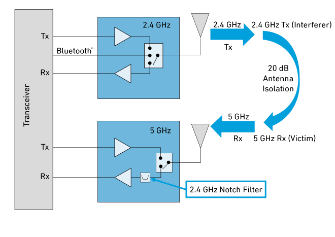
Figure 7. DBDC Filter Rejection in 2.4 GHz Band
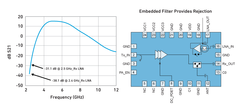
Figure 8. DBDC Out of Band Gain Data Sheet Specification
Looking Beyond the Data Sheet: Additional Important Parameters
Some other important parameters are typically not included in data sheets — but can still be critical to the success of your system design.
Burst length or packet aggregation
This measures the ability of the RFFE PA to support data bursting, which increases transmission throughput. If the PA is not capable of sending a long burst, then it will exhibit thermal transients, causing EVM degradation. This also causes throughput loss, takes up airtime, creates system latency and can increase the probability of coexistence issues. This data is typically not on the data sheet but can be requested from the component manufacturer. It is always a good practice to request this data, and to make certain that the part manufacturer provides specifications for both long and short packet bursts – up to 4 ms for long bursts and 180 us for short bursts.
PCB landing pattern
More information than just the data sheet is sometimes needed to ensure an optimal PCB layout. Before deciding on the PCB layout for your RFFE, make certain you review the following items for the RFFE components:
- Data sheets
- Application notes
- Manufacturing notes
- PC board Gerber files
In some cases, it may not be possible to use a PCB layout that exactly matches the materials and design shown in these documents (in terms of PCB via holes, board stack, board material, etc.). In these cases, work closely with your RF component manufacturer early in your design to ensure an optimal outcome.
Summary
Comparing data sheets between vendors can be difficult. Some manufacturers reduce design issues by including all the information you need on their data sheets, but others do not. In some cases, the specifications may not only be incomplete but also fail to reflect performance in real Wi-Fi applications. It may also be necessary to ask vendors for additional information that is important for your system design. A complete understanding of the critical parameters and how they relate to your application will help you produce a good system design that meets all the required regional specifications.