The Easy Way to a 1 Gbps RF Front-End on Smartphones
September 29, 2017

One could ask, “Why do we need 1 Gbps download speeds? Aren’t current download speeds fast enough?” Let’s face it: we all hate watching that spinning buffering symbol on our phones, and we always want more data. Carriers want you to have faster downloads too – the faster you get the data, the faster they can shift those valuable spectrum resources to another user.
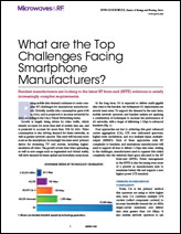
In a March 2017 report, Cisco stated that average mobile network connection speeds are currently around 6.8 Mbps – a far cry from 1 Gbps. No wonder we see the buffering symbol spinning on our phone during downloads.
So how can we get to 1 Gbps download and upload speeds on a
smartphone? Once you understand the enabling technologies for 1 Gbps and the
available RF components, you’ll see that there is an easy incremental
path to phones achieving gigabit LTE data rates.
The Steps to 1 Gbps: What’s Needed
First, let’s be clear: The road to gigabit LTE is not a jump. Instead it’s a series of small steps in the right direction.
Some background. The RF front-end (RFFE) remains one of the most critical aspects of mobile handset designs. Expanding carrier aggregation (CA) abilities, more complex antenna architectures, antenna tuning, higher-order modulation schemes, and the increase in spatial streams are all making the RFFE design more complex. Also, the move from LTE-Advanced to LTE-Advanced Pro to 5G New Radio (NR) drastically increases the RFFE complexity. In just the past few years, premium smartphones have moved from a handful of RF bands to as many as 34 bands in a single smartphone SKU.
But what is specifically needed to get to 1 Gbps? Let’s
outline some basic enablers:
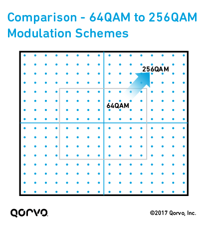
- Higher order modulation. On the downlink, going from 64 QAM to 256 QAM increases the speed of a single 10 MHz channel from 75 Mbps to 100 Mbps.
- Carrier aggregation. Multiply that 100 Mbps by the number of aggregated component carriers. 3-5 downlink (DL) CA is now available, so this allows for up to 500 Mbps.
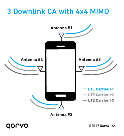
- 4x4 MIMO (multiple input/multiple output). With 4-antenna spatial diversity in LTE, a DL component carrier (CC) can effectively be expanded to 4 channels.
The most direct way to 1 Gbps is to use 3DL CA with 4x4 MIMO on 2 of the 3 component carriers. That’s effectively 10 streams of data in 3 bands. With 256 QAM, that’s 10 x 100 Mbps – which equals 1 Gbps. With a high-performance chipset, 3CA with 4x4 MIMO and 256 QAM functionality can be enabled in the mobile phone, but the RFFE has to be capable.
Because low band is not optimal for 4x4 MIMO due to constraints on antenna size, the bands supporting 4x4 MIMO need to be in one of the following frequency ranges:
- Mid-band (MB)
- High-band (HB)
- Ultra-high-band (UHB; ~3.5 GHz)
- 5 GHz range using Licensed Assisted Access (LAA)
If we start with available networks and RFFE architectures in phones today,
it’s difficult to consider UHB or LAA as readily available options, so
we’ll focus on adding 4x4 MIMO into the mid- and high bands.
A Baseline RFFE in Today’s Smartphones
LTE phones have been stepping toward this 1 Gbps
goal for some time, primarily by increasing the number of transmit (Tx)
and receive (Rx) paths with CA using multiplexers and/or adding more
antennas supporting a multitude of frequency bands. Many phones now have 4
radio antennas not including the Wi-Fi antenna – but not necessarily
to support 4x4 MIMO.
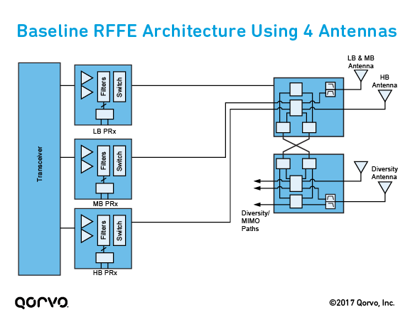
Below is a simple front-end design using 4 antennas (2 main antennas and 2 diversity/MIMO antennas). This design is a good baseline of what is now available in several smartphones on the market. It’s a simple high/mid/low-band module design that allows for at least 3 CA and covers high-, mid- and low-band LTE frequency ranges. The low-band and midband frequencies are supported by diplexing onto two antennas, while the high band is supported on the other two antennas. The antenna separation/isolation also allows for CA between high band and midband and/or low band.
Incremental Steps to Gigabit LTE Data Rates
With 4 antennas, we have the first requirement for 4x4 MIMO, but those 4 antennas need to be routed to 4 unique radio paths for each spatial stream. Simply put, the configuration where high band had 2 dedicated antennas and midband had 2 dedicated antennas would not support 4 mid/high antennas. It also means we can’t simply rely on antenna isolation to multiplex midband and high-band frequencies, at least not without more antennas.
If we follow the plan of 2 CCs supporting 4x4 MIMO, then we should look to have 8 spatial streams in mid- and high bands. We need to have a way to split out the individual bands on all four antennas – essentially, we need a way to multiplex mid- and high bands. We can assemble an incremental architecture by adding mid/high diplexing on the midband antennas and on the high-band antennas.
But it’s not always simple to add fixed multiplexers into an existing lineup. A diplexer that splits midband and high-band frequencies is often very lossy, which degrades Rx sensitivity and leads to increased Tx power requirements from power amplifiers. There are implications for current consumption and PA + filter ruggedness to consider as well.
Another option is to include components with multiple mid/high multiplexers
(i.e., hexaplexers or septaplexers) to support all the band combinations, but
this can be an expensive path forward and quite a deviation from proven
designs.
Qorvo’s Approach to 1 Gbps: Switched Multiplexers
So, what is the easy step forward on the Qorvo RFFE to achieve 1 Gbps? Flexible mid/high diplexing using switched multiplexers, such as the Qorvo QM17001.
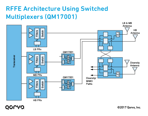
With the QM17001, three configurations can enable a 1 Gbps front-end with little added space and low impact on current proven components. These three configurations are:
- A low-loss bypass. For low impact when not using 4x4 MIMO
- Mid/high diplexing path 1. Standard mid/high diplexing that covers most bands
- Mid/high diplexing path 2. Enabling the difficult cases of multiplexing B30/B40 with midband or high band
The radio supports the following modes using the configurations listed
above:
- Single band LTE (Configuration 1). The low insertion loss bypass means little impact to current architecture specifications.
- DL CA (Configuration 1). Mid/high diplexing without MIMO can still be supported with antenna isolation.
- 4x4 MIMO, single band (Configuration 1, 2 or 3). For high band, QM17001 can be enabled on the midband paths, creating a route for additional receivers. A similar configuration is possible for midband using the QM17001 on the high-band paths. The primary Tx path is still in bypass mode, so the impact is low.
- 4x4 MIMO, mid/high diplexed (1 Gbps) (Configuration 2 or 3). All QM17001’s are enabled and the mid/high diplexers introduce loss.
In summary, you can achieve a 1 Gbps LTE RFFE with incremental changes to
existing architectures, and Qorvo is here to help you make that happen. For more information, visit Qorvo’s RF Fusion™ web
page. For technical guidance and applications support, please visit our Technical
Support web page.
Have another topic that you would like Qorvo experts to cover? Email your suggestions to the Qorvo Blog team and it could be featured in an upcoming post. Please include your contact information in the body of the email.

Gigabit Data Rates on Smartphones
Read the technical details how to achieve it in 4G LTE, in our article published on Microwaves & RF.
Download Now >