Facts About Noise Figure in 5G and Defense Systems
September 28, 2021
System designers are always looking for simple solutions for their complex system designs. Well, look no further for RF front-end receiver solutions in the defense, aerospace, and 5G wireless infrastructure realm. This blog post is a practical guide to reducing design complexity while meeting those tough noise figure requirements for 5G infrastructure, defense, and aerospace applications.
A Brief Review on Receiver Noise Figure
Many RF front-end (RFFE) systems are unique, but the receivers are similar in many ways. In general, RF sensitivity is a key specification of all wireless radio receivers. RF sensitivity is defined as the minimum input signal level to the receiver, that can be detected with a certain modulation scheme, without dropping below a specified error rate. The RF receiver’s ability to pick up the required level of radio signals while ignoring the unwanted ones will enable it to operate more effectively within the application.

Some of the parameters that affect the RF sensitivity of a receiver are:
- Signal to Noise Ratio (SNR) – This is the ratio of the given signal power level to the noise within the system for a certain bandwidth.
- Noise Figure (NF) – The NF is a measure of how signal to noise ratio (SNR) degrades while passing through a system. It specifies the amount of noise added by a component as the signal passes through it.
- Bit Error Rate (BER) – This is a form of measurement used for digital systems. As the signal level falls or the link quality degrades, the number of errors in the transmission or bit errors increases. Measuring the BER gives an indication of the SNR but in a format that is often more useful for the digital domain.
- Error Vector Magnitude (EVM) – EVM is a measurement used to quantify the performance of a digital radio transmitter and receiver with a complex I-Q Amplitude modulation scheme. A signal sent by an ideal transmitter or received by a receiver would have all I-Q signal constellation points precisely at the ideal locations. Still, imperfections such as noise, distortion, phase noise, etc., cause the actual constellation points to deviate from the ideal locations. The EVM is a measure of how far from the ideal positions the actual received data elements are.
Low noise amplifiers (LNA) usually have less issues in amplifying the signal levels, instead, the limiting factor tends to be restricting the noise, as it masks the wanted signal. Two critical performance considerations are receiver sensitivity and SNR for wireless communications, radars, instrumentation, satellites, and others.
In terms of a receiver’s noise performance, it is typically the first stage or the LNA that dictates the overall noise figure of the entire radio receiver. Optimizing the SNR and NF of the LNA, improves the receiver’s signal detection capabilities, and reduces the signal Bit Error Rate.
5G Receivers
In the 5G, defense, and aerospace arenas, the bandwidths of LNA's and other system components are increasing to achieve higher levels of data capacity and throughput required to handle today's applications. This bandwidth increase means higher demands for noise figure optimization and more challenging tasks for system designs.
Network densification is a must to implement 5G effectively. Increasing the number of access points per area and implementing more transmitters and receivers at each access point boosts densification. This boost improves the spectrum and network efficiency, increases area traffic capacity, and with the use of high dynamic range transceivers with better sensitivity, these systems are making 5G possible. Moreover, more antennas are being added to these access points to help increase spatial streams – to improve capacity and signal reliability
LTE systems have been using Multiple-Input Multiple-Output (MIMO) to increase signal reliability by using diversity and spatial multiplexing. Both, diversity, and spatial multiplexing provides greater immunity to channel fading which improves uplink system capacity while using high data modulation schemes which require high SNR.
Many 4G LTE systems have already moved to 5G. MIMO is even more critical for 5G due to the possibility of deployment at much higher frequencies compared to 4G LTE systems. These 5G systems have massive-MIMO capability, which is an extension beyond traditional MIMO, offering a much higher number of antennas, like 32, 64, 128 array configurations on base station antenna systems, as shown in Figure 1. By controlling the phase and the amplitude of the antenna elements, these antenna arrays can focus the energy to a certain point in space. This increases the signal directivity and thus improves the achievable data rates. It also increases signal range while suppressing the unwanted interference to other frequency bands and wireless systems.
5G networks have very high bandwidth capability due to the many new frequency spectrums with higher bandwidths. For example, Frequency Range FR1 (410 MHz – 7125 MHz) can have transmission bandwidths up to 100 MHz per channel with multiple channels simultaneously. With development of semiconductor technologies, LNA designs are now covering very wide bandwidth to accommodate several 5G bands, allowing for easier system channelization design. To achieve these wide-band capabilities, the LNA must have superior noise figure and EVM capabilities across the entire bandwidth. Additionally, small form factors for these components are desirable because these RFFE components now reside at the top of the tower close to the antenna with a large number of elements.
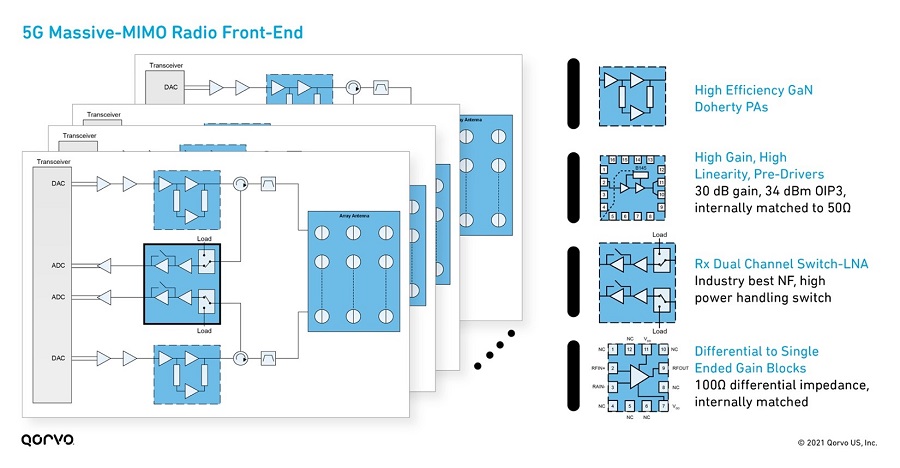
Figure 1: Components of an RF Front-End
Since 5G uses a TDD transmission scheme, the receiver front-end is more susceptible to failure from a high-powered signal transmitted from a radio's power amplifier during transmit mode operation. Hence the first stage LNA should be capable of handling greater than 20 dBm of input power level. This adds stringent robustness requirements on the first stage LNA. Apart from TDD operation, any antenna fault arising on the network equipment could also lead to high power getting reflected into the receiver. LNAs used for this application which are not rated for high input power levels will have decreased reliability, inferior performance, and degraded noise figure. A damaged receiver front-end can lead to downtime and loss of service, impacting network provider's revenue on top of expensive site repairs.
Defense and Aerospace Receivers
Demanding requirements and new technology developments drives defense and aerospace (D&A) RFFE systems to evolve quickly – especially in the military radar, satcom, electronic warfare communications and digital receivers. Figure 2 shows different RFFE block diagrams for various D&A applications. With recent semiconductor advancements there is a clear push for devices with small form-factor, lightweight, and high level of integration in both transmit and receive sections. Similar to 5G, as one would expect, these features are just as appealing to the defense and aerospace arena and aligned with the SWaP – size, weight, and power – objective.
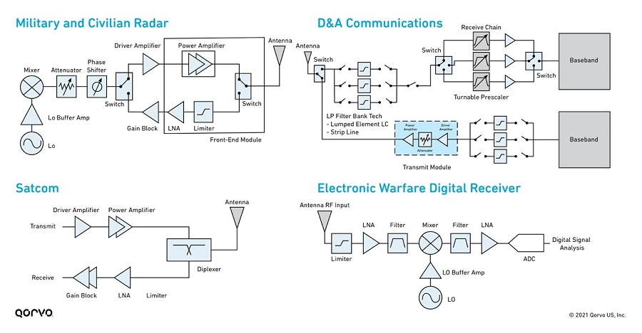
Figure 2: Examples of RFFE's used in defense and aerospace
Receiver products in D&A not only require high gain and power capability for best-in-class amplification, they also require the ability to survive extreme conditions like those in the infrastructure arena. The survivability function is usually needed at much higher input levels in the kilowatts range with resistance to jamming over a wider frequency bandwidth, in addition once subjected to high RF stress, these devices should be able to recover quickly for communications. This is required in primarily military, aerospace radar, and military communication applications, where electronic countermeasures (ECMs) might be used to overwhelm a receiver as a defense tactic.
In the past, D&A digital receivers have been narrowband due to limitations with technology. But this has changed, as new technology advancements in Gallium Arsenide, Gallium Nitride and Silicon have allowed for larger sustainable bandwidths. This has brought an onset of many new D&A applications and features to existing products.
Many military applications require this wide-band and multiband communications with low probability of being intercepted and detected. With the addition of frequency hopping to mitigate signal detection, these systems incorporate wide bandwidth and spectrum for transmission and receiving. These aspects can lead to more noise degradation on the receiver and a reduction of input power handling. Also, if a receiver is exposed to high power levels for an extensive amount of time, the components' performance / reliability will degrade and can even lead to catastrophic failures. Therefore, it is imperative designers take the necessary steps to ensure reliability and receiver sensitivity.
Optimizing Noise Performance
Ultimately, each individual application in the above-mentioned areas drives system design and requirements. But, at a high level, some RF front-end requirements remain the same.
The receiver noise performance always starts at the first stage of the RFFE. At the RFFE, the signal levels are at their lowest, and if the noise power level is comparable to the signal, it is difficult to determine what is noise and what is the incoming signal. It is imperative that a high SNR is maintained throughout the receiver system.
Any practical receiver will not have an LNA just after the receiving antenna. In most cases there will be some passive lossy components, such as couplers, filters or even PC board traces connecting the antenna to the input of the LNA. Hence it is critical to minimize any losses before the first stage LNA, since any loss before it will increase the total NF by the same amount. This means that any passive components designed before the first stage LNA must be selected with proper consideration during the lineup analysis. Front end filters usually have higher insertion loss at band edges compared to middle of the band. Such variations across the band of interest should also be accounted for, apart from part-to-part variation in insertion loss of these passive components.
The NF of the receiver lineup is dominated by the NF of the first active amplifying stage since the effect of the subsequent stages is reduced by the gain of the first active amplifying stage. Hence it is important to choose an LNA with high gain and very low NF as the first stage amplification block. Any element with higher NF after this LNA will have very little effect on the total lineup noise figure.
Another important consideration for the receiver LNA is its performance over temperature. Temperature plays a significant factor in the NF and Gain variation over the entire frequency range and the stability of the LNA. Since modern transmiter / receiver (T/R) design will integrate the receiving and transmitting channel together in outdoor units, proper ventilation of the LNA or front-end with heatsinks or heat-dissipating techniques will stablize the system performance to ensure proper signal receiving and transmitting. Some applications in radio astronomy use cryo-cooling to control module temperature.
It is also important to minimize any mismatch before the LNA since it will result in losses which will directly add to the total NF of the receiver. This can sometimes be hard to exercise since the input to the LNA might come through multiple layers or transition vias. 3D EM simulation of input traces can help model these transition vias for optimal dimensions and minimize any mismatch that may be caused by them.
The modulation scheme employed in a system determines how much noise degradation is acceptable to maintain a reliable communication link, since these digital modulation schemes requires a certain level of system SNR. The higher the order of the digital modulation scheme, the higher the SNR needed to continue transmission of data using that modulation scheme. Switching to lower order digital modulation schemes, which require low SNR to operate, in the presence of noise enables the communication link to be maintained between the wireless systems, albeit with lower data rates.
Another aspect to consider minimizing unwanted NF degradation, is by ensuring the LNA is being operated within its recommended operating condition. Biasing at different voltage, providing higher than maximum rated input power, and operating outside the designed frequency band can all degrade the NF of the LNA. Continuous operation of the LNA outside its recommended operating conditions can also degrade reliability of the device causing shorter operating lifetime besides other performance parameters degradation, such as gain etc.
Designers must make crucial tradeoffs between parameters like gain, gain flatness, input/output match, linearity, power consumption and size, while keeping the system stable over the full range of operating conditions. While a low receiver noise figure is the primary goal of system design, there are always tradeoffs a system designer must make such as sacrificing NF, return loss to improve other parameters. Qorvo's helpful cascade analysis calculator, shown in Figure 3, can assist in providing a starting point in these system-level designs and tradeoffs.
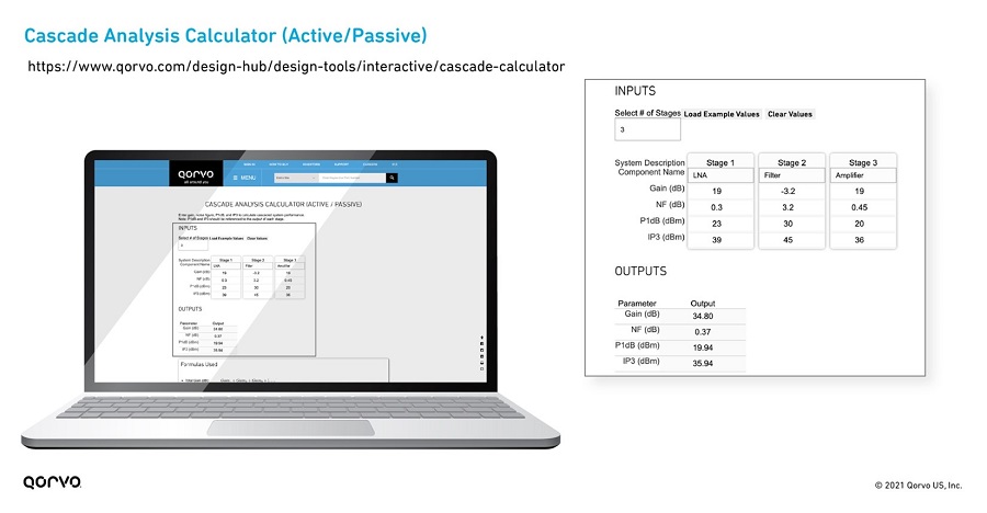
Figure 3: Qorvo's Cascade Calculator on the Design Hub
Limiter Impacts on D&A Receivers
As noted earlier, an LNA's high input power capability is important. A method to reduce the possible impact of high input power to the receiver is to add a limiter at the input. This does help with protection but has a side effect of increasing the noise seen at the LNA. This fix also reduces the sensitivity of the receiver – reducing signal range, through-put, and performance. Therefore, if you pick an LNA with very high input power, the limiter would not be needed, helping the overall receiver performance.
Ultimately, the NF and system linearity affect receiver sensitivity. Tradeoffs among several key parameters like gain, matching, linearity, and bandwidth must be analyzed to achieve optimum receiver sensitivity performance — all while keeping a close eye on interferences, temperature, and the ability to sustain receiver attacks.
Some final thoughts
The NF and SNR are critical for receiver system performance. Tradeoffs among several key parameters like gain, matching, linearity and bandwidth must be evaluated to achieve optimum receiver sensitivity while keeping a close eye on interferences, temperature, and the ability to sustain receiver attacks. Below listed some major factor to consider while design for a wireless microwave receiver system.
- Use the best LNA with the least amount of noise in your design.
- Design your system with the applications true nominal temperature in mind.
- Isolate or prevent external noise from affecting the performance or input of the receiver by shielding or eliminating the source.
- Proper bypassing of the DC power supplying circuit will reduce noise coupling.
- Avoid using lossy elements along the signal path up to the LNA input.
- Ensure there are proper design of RF impedances on both the input and output of the LNA
- A GaN device will have an inherently high robustness compared to GaAs parts. Using GaN device rather than a GaAs technology part with a limiter also helps lower the noise figure as a limiter will add some noise to the system.
Have another topic that you would like Qorvo experts to cover? Email your suggestions to the Qorvo Blog team and it could be featured in an upcoming post. Please include your contact information in the body of the email.