Each successive Wi-Fi generation offers higher data rates and more capacity, but also presents more challenging requirements for Wi-Fi product design. The Wi-Fi 5 standard used in many current products achieves up to 866 Mbps downlink data rates over a single RF channel, and up to 6933 Mbps using 160 MHz channels and eight simultaneous data streams. It offers 8x8 MU-MIMO (Multi-user Multiple Input Multiple Output) and uses 256 QAM (Quadrature Amplitude Modulation). It's a big step up from the previous Wi-Fi 4 standard, which supported only 600 Mbps maximum downlink data rates using 4x4 MIMO. The next generation, Wi-Fi 6, adds 1024 QAM and OFDMA (Orthogonal Frequency Division Multiple Access), to achieve even higher uplink and downlink speeds up to about 9600 Mbps.
To build a differentiated product that meets the increasingly challenging requirements of new Wi-Fi generations, you need a combination of the best software and the best hardware. First, you need the RF front end to provide exceptional output power and range together with low current consumption and high efficiency. Second, you need to include best-in-class coexistence and support for multiple standards in a single package. In this article we explore how to combine software and hardware strategies to achieve these two key goals and create a best-in-class Wi-Fi product.
The PA and Digital Pre-Distortion (DPD)
The PA is the most critical component of the RF radio in a Wi-Fi transmitter. The PA's performance affects range, coverage area, data rate, capacity and power consumption. Wi-Fi access points typically transmit between 100 mW and 1 W of RF output power. The PA must be able to generate this power with minimal non-linear distortion.
Each Wi-Fi generation requires a major improvement in PA linearity. To meet this requirement, it is essential to use new, higher-linearity PA hardware, together with digital pre-distortion (DPD), a software-based method for removing distortion using digital signal processing techniques. Though the PA hardware provides most of the linearity improvement, DPD makes a smaller but essential contribution. DPD uses software models to measure the nonlinearity of the PA and create an inverse signal using a software-enabled pre-distortion algorithm, which then linearizes the PA output signal.
A widely used Wi-Fi PA linearity measurement is Error Vector Magnitude (EVM). EVM quantifies the performance of a digital communications channel, measuring the deviation of captured encoded data symbols from their ideal locations within the I/Q constellation. The PA must deliver acceptable EVM over the full operating range of power output and channel frequencies.
Figure 1 illustrates the increasingly stringent EVM System specifications required for the most recent Wi-Fi standards.
Figure 1: EVM System Specifications for Wi-Fi 4, 5, and 6
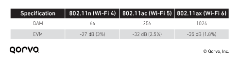
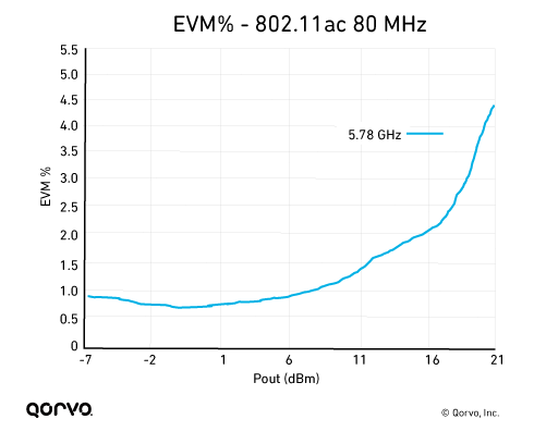
Figure 2 shows typical EVM PA measurements as output power increases. As shown, EVM degradation occurs at high output power levels above 11 dBm. As PA output increases and enters the gain compression region, non-linear distortion occurs causing EVM to increase.
For a Wi-Fi 5 application, this PA needs to deliver output power above 16 dBm and therefore cannot meet the specification of 2.5% (-32 dB) EVM; its linear output power is insufficient for a Wi-Fi 6 transmitter design. Additional linearization is needed to meet the specification.
Figure 2: Example PA EVM % vs. Pout Measurement
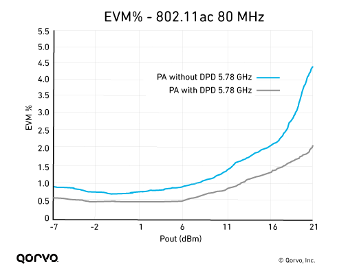
As shown in Figure 3, using DPD with the PA provides this additional linearization, enabling the PA to meet the Wi-Fi 5 EVM specification of 2.5% (-32 dB).
Figure 3: Example PA EVM % vs. Pout Measurement – with and without DPD
One major impact of non-linear distortion is adjacent channel leakage: transmission in frequencies outside the Wi-Fi band. As shown in Figure 4, DPD greatly reduces adjacent channel leakage.
Figure 4: Example PA Output Spectrum Measurement – with and without DPD

Best Solution to Wi-Fi Interference – Software, Hardware or both?
Interference can occur inside a Wi-Fi device or between devices. For example, interference can occur between Wi-Fi and wireless signals from carriers such as AT&T and Verizon; there can also be interference between different wireless standards supported within an access point. The most common scenarios involve interference between Wi-Fi and Bluetooth or LTE, because those technologies are so widespread.
Three main types of interference are important for Wi-Fi product design.
- Non-Wi-Fi interference. This involves devices that operate in frequencies outside the Wi-Fi bands. It typically occurs when a device such as an LTE phone or cordless handset transmits noise in the Wi-Fi spectrum, interfering with Wi-Fi reception.
- Adjacent channel interference. This occurs when Wi-Fi devices in close proximity operate in the same spectrum range but on different channels that overlap. These devices essentially talk over each other.
- Co-channel interference. Devices operate on identical frequencies but use different radios; each client and access point compete for the same airtime. Co-channel interference can occur between 2.4 GHz Wi-Fi and Bluetooth, Zigbee or Thread, for example. Co-channel interference can also occur between different radios on the same device.
Non-Wi-Fi and adjacent channel interference must be addressed using hardware solutions such as bulk acoustic wave (BAW) Wi-Fi coexistence or bandedge filters, as we'll discuss in the following paragraphs. Co-channel interference is solved by establishing coordination between RF radios using a combination of software and hardware. By using a solution that combines intelligent software with a system-on-a-chip (SOC) you can eliminate much if not all of the co-channel interference.
The best solution for non-Wi-Fi and adjacent channel interference is filtering. BAW filters, along with intelligent software, effectively eliminate interference between Wi-Fi and adjacent frequencies, and also provides a scalable solution. They prevent devices such as cell phones from interfering with Wi-Fi reception, and they allow Wi-Fi access points to utilize the full Wi-Fi spectrum for transmissions without the risk of interfering with adjacent bands.
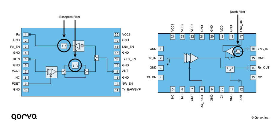
Interference can also occur within devices that have multiple antennas as well as multiple radios (e.g. Wi-Fi, Bluetooth, Zigbee, and Thread). Proper antenna isolation is paramount to mitigate the potential for coupling between antennas. Without proper isolation, a transmit signal from one antenna can generate increased noise at a receiver on the same device, negatively impacting the signal-to-noise ratio and desensitizing the receiver.
Currently, no software algorithms exist that can effectively increase antenna isolation or decrease desensitization. The only resolution is to add bandpass or notch filtering. Figure 5 shows two examples of front-end modules with embedded filters. Using integrated modules with embedded filters, as opposed to discrete components, is the best approach because it reduces the need for external tuning, requires less board space and simplifies design.
Figure 5: Wi-Fi Front-End Modules with Embedded BAW Filters
Takeaways
Hardware and software are equally important when designing a best-in-class Wi-Fi product. Cohesively integrating software and hardware can help you optimize RF front-end performance, maximizing output power and efficiency and minimizing power consumption. A combination of software and hardware also helps to increase linearity and meet interface requirements set by regional certifying bodies. Integrated front-end modules typically provide the best solutions. They help reduce design time and are typically engineered with enough headroom to meet regional requirements, increasing the likelihood that the final Wi-Fi product will achieve certification.