UnitedSiC’s FET-Jet Calculator – Taking the Guesswork out of SiC FET Selection
March 16, 2021
This blog post was first published by United Silicon Carbide (UnitedSiC) which joined the Qorvo family in November 2021. UnitedSiC is a leading manufacturer of silicon carbide (SiC) power semiconductors and expands Qorvo's reach into the fast-growing markets for electric vehicles (EVs), industrial power, circuit protection, renewables and data center power.
Power supply design tools are continually improving, with simulation increasingly able to output accurate waveforms and performance in terms of regulation, efficiency and resulting losses. There is a small problem, though: the simulator can only work with what you tell it – the software is clever, but it won’t choose a power transistor for you, and it certainly won’t tell you if you have chosen one that isn’t optimum or even breaks under normal circuit stresses.
Designers will have a pretty good idea about the switch technology to use – they won’t choose an IGBT for MHz switching or a silicon MOSFET for high-power traction applications, so perhaps they will take the sensible option and consider a UnitedSiC SiC FET as a starting point, with its close-to-ideal switching performance and low conduction losses. The range available is wide, with different voltage ratings, on-resistances and package styles, and there is always the option to parallel parts. An optimum SiC FET for performance and cost can be found, but until now, it has meant tediously iterating through simulation or bench testing with different parts. Now, UnitedSiC’s online FET-Jet Calculator has changed all that.
The calculator takes care of that initial part selection. The tool is free-to-use without any registration and enables a designer to select an application, topology, electrical design parameters and ambient temperature, and quickly try a device from UnitedSiC’s range of SiC FETs and diodes with a chosen heatsink rating. Critical performance results are instantly calculated, including overall efficiency, with component losses separated out into dynamic and conduction contributions, along with junction temperatures and current stress levels. If a resulting voltage is above the rating of the selected part, a warning is given.
Delving a little deeper, the applications that can be selected are AC-DC front-ends and isolated or non-isolated DC-DC converters. Within each application, a topology can be chosen from the most popular. For example, in the AC-DC category, a traditional boost PFC, Totem Pole PFC, Vienna Rectifier, or Two-Level Voltage Source Inverter is featured. In the non-isolated DC-DC category, buck or boost can be selected with or without synchronous rectification along with the three-level boost topology. In the isolated DC-DC category, the popular LLC converter can be selected, in either half or full bridge variants, along with the Phase-Shift Full bridge or Dual Active Bridge with phase shift control. Where relevant, conduction modes from continuous (CCM) to boundary (BCM) are supported.
SiC FETs and diodes from the UnitedSiC range can be selected from drop-down menus, which are regularly updated with the latest device releases and, helpfully, clicking on a device links to its product page with links to the datasheet and SPICE model. The displayed list of devices can also be sorted by rated voltage, package and series, with a slider restricting the selection to a rated current range.
An example is the best way to show the power of the calculator; if we select a Phase Shift Full Bridge topology in the isolated DC-DC section, we see the screen below.
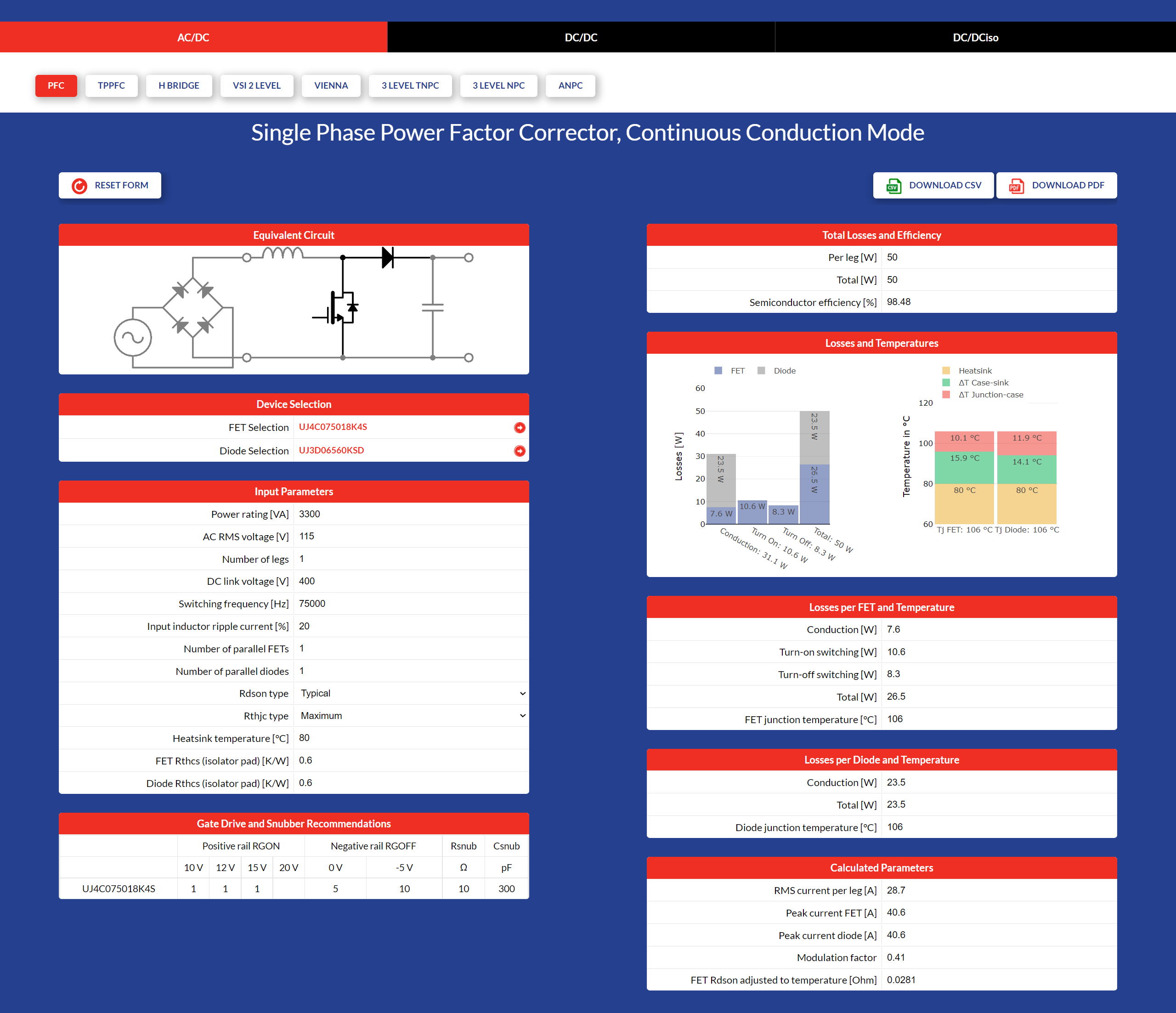
Figure 1: An example screenshot of the UnitedSiC FET-Jet calculator
Here we have selected 400V/12kW output from an input supply of 800V. The switching frequency is set at 80kHz and parameters specific to a PSFB topology are input such as desired peak-to-peak inductor ripple current, maximum primary phase shift, maximum duty cycle loss, transformer primary capacitance and turns ratio. A maximum heatsink temperature can be specified, along with thermal resistance from the switches to heatsink through isolating pads. Note that device on-resistance and thermal resistance from junction to case can be set as ‘typical’ or ‘maximum’ to allow for worst-case analysis.
With a UF3C120080K4S device selected, the calculator instantly returns average and rms switch currents in forward and reverse, along with a full breakdown of conduction and switching losses, yielding a creditable overall efficiency of 99.25% for the semiconductors. Now you can play and see the effect of choosing other devices or operating conditions. For example, increasing switching frequency to 200kHz increases losses by 19% with the same SiC FETs, but further calculations might show that the magnetic components are much smaller as a consequential benefit, which might justify the higher semiconductor losses. Try doubling the power to 24kW and a red warning appears that the device junction temperatures are over maximum ratings.
An interesting experiment is to set the number of parallel FETs in each position to more than one. Going back to our default settings, using two parallel FETs instead of one reduces overall losses by nearly half, with junction temperatures dropping by nearly 20 degrees. This is because the current is shared between the two devices, but as power is proportional to the square of the current, loss in each device goes to a quarter or a half for the pair compared with a single device. However, each FET runs much cooler with only a quarter of the conduction loss of a single part, so on-resistance is lower and losses lower still. This is offset by slightly higher switching losses for two FETs in parallel.
The initial selection of semiconductor switches for a power supply design can be a chore. UnitedSiC’s new FET-Jet CalculatorTM makes it easy and accurately predicts system performance. The versatile FET-Jet calculator will definitely appeal to designers who want a quick but reliable prediction of how UnitedSiC FETs will perform in a range of applications – it’s fun and free as well!
Try out the calculator here.
Have another topic that you would like Qorvo experts to cover? Email your suggestions to the Qorvo Blog team and it could be featured in an upcoming post. Please include your contact information in the body of the email.