Need Space-saving Tips for Your next Smartphone Design? Here’s How
December 12, 2022
Today's smartphones are not growing in size, but the content inside is. With the ever-increasing number of cameras, sensors and components to accommodate today's new features, the available layout is shrinking. This is no different for the accessible area for the antenna.
This situation becomes more pronounced as more antenna capability is needed to accommodate 5G new radio (NR) bands. But there are new components and application techniques designers can implement to help meet the challenge of limited space. Using antennaplexers is one of those design options.
Using antennaplexers, design engineers can compress this antenna area to save space. We illustrate two design scenarios – one with and one without using the QM28005 antennaplexer for a GPS and Wi-Fi antenna layout. In Figure 1, we see a typical layout design for a GPS, GNSS (Global Navigation Satellite System), and Wi-Fi antenna. We will call this design layout scenario 1.
As shown, the design is taking up a large amount of PC board landscape to accommodate all antennas associated with these bands.
To consolidate these bands, we use the QM28005 antennaplexer. The QM28005 is a compact filter module designed to meet the strict requirements of out-of-band attenuation while optimizing for insertion loss of L5 GPS, L1, 2.4G and 5G Wi-Fi. See Figure 2.
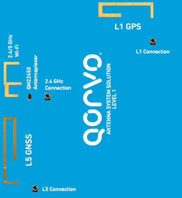
Figure 1: Typical GPS, GNSS and Wi-Fi (2.4/5 GHz) antenna layout – design scenario 1.
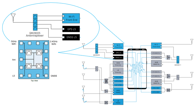
Figure 2: Functional block diagram of QM28005.
The GPS and Wi-Fi antenna was designed so a single antenna (ANT) geometry could radiate over the L1, L5 and 2.4/5G Wi-Fi bands to interface with the QM28005. Below, Figure 3 illustrates the design of this antenna.
Let's compare the GPS and Wi-Fi antenna design with and without using the QM28005 antennaplexer. In Figure 3 below, using the QM28005 antennaplexer encourages a design that compresses the GPS and Wi-Fi bands into one area – as shown on the right side of the figure. While the left image – the antenna design without the QM28005 antennaplexer does not.
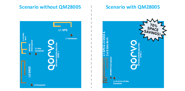
Figure 3: Layout design for GPS and Wi-Fi antennas with and without QM28005.
| Antenna Band Layout | Three Antenna Layout Without QM28005 | Three Antenna Layout With QM28005 |
| L1 | 208 mm2 | N/A |
| L5 + 2.4/5 GHz Wi-Fi | 392 mm2 | N/A |
| L1 + L5 + 2.4/5 GHz Wi-Fi | N/A | 180 mm2 |
Table 1: Comparison of layout dimensions using QM28005 antennaplexer.
Comparing the two antenna design scenarios, we can see that there is over a 70% space reduction comparing the 600mm2 antenna area not using the antennaplexer compared to the 180mm2 solution using the QM28005.
Additionally, the components used to interface with the consolidated antenna through the use of the QM28005 antennaplexer could result in a lower BOM cost as the number of components required to interface with a single antenna rather than individual multiple antennas would be reduced.
Qorvo can help you achieve a design that meets your customer needs. For more detailed information on this described application, please contact a Qorvo Sales Representative to connect with our tech experts.
Have another topic that you would like Qorvo experts to cover? Email your suggestions to the Qorvo Blog team and it could be featured in an upcoming post. Please include your contact information in the body of the email.